In-situ testing in Bristol delivers direct ground data essential for navigating the region’s varied geology, from the limestone of the Avon Gorge to the soft alluvial clays of the city centre. These investigations provide immediate strength and deformation parameters without the disturbance of sampling, complying with BS 5930 and Eurocode 7. A cornerstone for earthworks verification is the field density test (sand cone method), which confirms compaction levels right at the surface.
This category supports foundation design for residential developments, warehouse slabs, and highway embankments across the South West. Beyond density control, in-situ methods also validate bearing capacity and stiffness for shallow footings, often paired with plate load testing to satisfy building control. For deeper soil profiling, the data is routinely correlated with cone penetration testing (CPT), creating a robust geotechnical model from the ground down.
Anchor bond capacity in Bristol's Mercia Mudstone can drop by 40% when the moisture content increases by just 3%, a sensitivity that standard presumptive values completely overlook.
How we work
Local ground factors
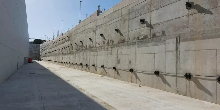
Bristol recorded a 4.1 magnitude earthquake in 2007 with an epicentre just 15 kilometres north of the city centre, a reminder that the UK is not seismically inert. While the peak ground acceleration was modest — on the order of 0.02g — the event highlighted how few retaining structures in the city had been assessed for even minimal cyclic degradation of anchor bond. A passive anchor system subjected to repeated micro-strain cycles can lose up to 15% of its residual capacity within the first ten load reversals, particularly in the silt-rich weathered zone of the Penarth Group that underlies much of the Harbourside. Our post-earthquake forensic reviews of anchored excavations in the Floating Harbour area have consistently shown that the critical failure mode is not tendon rupture but grout-to-ground interface deterioration. For that reason, every anchor design we issue for Bristol includes a corrosion protection classification (CP3 or CP4 depending on aggressivity) and a defined monitoring schedule, because a hidden anchor is not a maintenance-free anchor.
Relevant standards
BS 8081:2015 – Code of practice for grouted anchors, BS EN 1997-1:2004 (Eurocode 7) – Geotechnical design, BS EN 1537:2013 – Execution of special geotechnical works: Ground anchors, BS 5930:2015 – Code of practice for ground investigations, CIRIA Report C760 – Guidance on embedded retaining wall design
Related services
Active anchor design and testing specification
Full Ultimate Limit State and Serviceability Limit State design of prestressed ground anchors for permanent retaining walls, including bond length calculation in variable Bristol geology, tendon selection (Dywidag bars or multi-strand systems), and site-specific suitability testing procedures to validate the grout-to-ground interface before production drilling begins.
Passive tie-back and soil nail verification
Design review and independent checking of passive anchor systems for temporary excavations, with particular attention to the deformation compatibility of the facing element. We verify the nail load distribution using in-house pull-out test data and assess the long-term durability of the system against the aggressive groundwater conditions common in the former docklands and the Avon floodplain.
Typical parameters
Common questions
What is the difference between active and passive anchor design, and which one does my Bristol project need?
An active anchor is prestressed to apply a deliberate force to the retained ground, limiting wall movement from the outset. A passive anchor only develops its reaction force as the wall moves and the ground deforms. Under Eurocode 7, permanent retaining walls in Bristol generally require active anchors because the allowable displacement adjacent to existing buildings is typically less than 0.2% of the excavation height. Passive anchors are more common for temporary works where slightly larger movements can be tolerated, but the design must still demonstrate that the mobilised force is compatible with the facing element's deformation capacity.
How do you determine the bond length in Bristol's variable ground conditions?
Bond length is calculated by dividing the design anchor load by the product of the tendon perimeter and the ultimate grout-to-ground bond stress, then applying a material factor. The critical variable is the bond stress, which we derive from laboratory interface shear tests on samples representative of the actual stratum — Mercia Mudstone, Redcliffe Sandstone, or the weathered Penarth Group. We never rely on presumptive values from tables alone, because the coefficient of variation in Bristol's Triassic materials can exceed 30%, and a bond length that is too short by 500 mm can reduce the anchor's characteristic resistance below the design action.
What testing is required to validate an anchor design?
BS 8081 and BS EN 1537 mandate a three-stage testing regime. Stage one is a suitability test on sacrificial anchors to confirm the design bond stress before production drilling. Stage two consists of proving tests on a minimum of 25% of production anchors, loaded to 1.5 times the working load. Stage three is an acceptance test on every anchor, with load-extension behaviour plotted against the theoretical elastic line. Creep testing for permanent anchors must run for at least 1,000 hours, with the creep rate stabilising below 2 mm per log cycle of time.
What is the typical cost range for anchor design services for a project in Bristol?
Anchor design fees for a typical Bristol project generally range from £760 for a single anchor verification to £3,220 for a full retaining wall anchor scheme with suitability testing specification and independent design check. The final figure depends on the number of anchor rows, the complexity of the ground profile, and whether the design requires finite element modelling to assess group effects.
How does corrosion protection affect the design life of an anchor in Bristol?
Corrosion protection is classified according to BS 8081 as CP2 through CP4, with CP3 and CP4 being mandatory for permanent anchors in aggressive environments. The groundwater in Bristol's docklands and the Avon floodplain is often brackish or contaminated with industrial leachate, which accelerates corrosion of unprotected steel. The protection system — typically corrugated plastic sheathing with factory-applied grout cover — adds 15–25 mm to the tendon diameter, which must be accounted for in the bond length calculation because it reduces the effective grout-to-ground contact perimeter.